Toyota Camry O2 Sensor Wiring Diagram Wiring Diagram
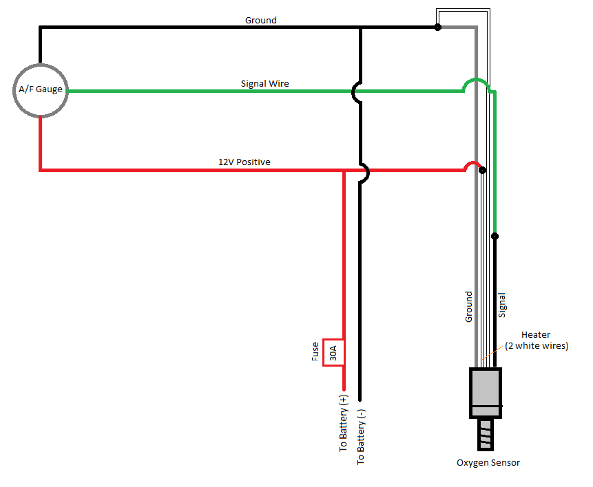
Wiring Diagrams for 4-Wire Oxygen Sensors: 4-wire oxygen sensors, also known as air-fuel ratio sensors, offer better precision compared to their 1, 2, and 3-wire counterparts. They consist of two wires for the heater circuit and two wires for the sensing element. The sensing element wires connect to the PCM, with one wire serving as the signal.

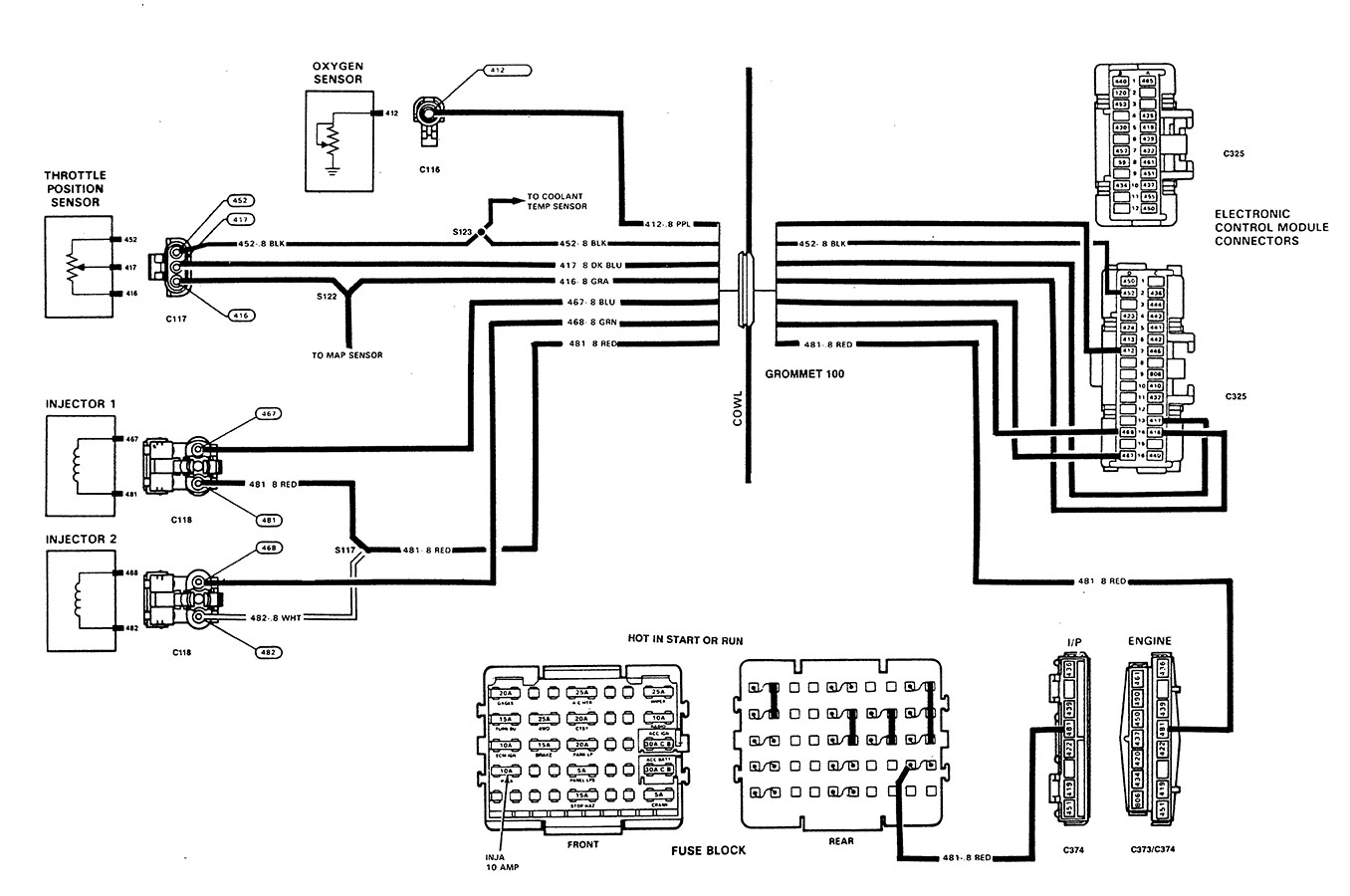
[DIAGRAM] Gm Oxygen Sensor Wiring Diagrams
The ground wire in a 4-wire O2 sensor wiring diagram is the foundation for the entire circuit. The signal wire in a 4-wire O2 sensor wiring diagram is responsible for transmitting information from the O2 sensor to the car's computer. The computer uses this information to adjust the air/fuel mixture in the engine and maintain optimal.
5.3 O2 Sensor Wiring
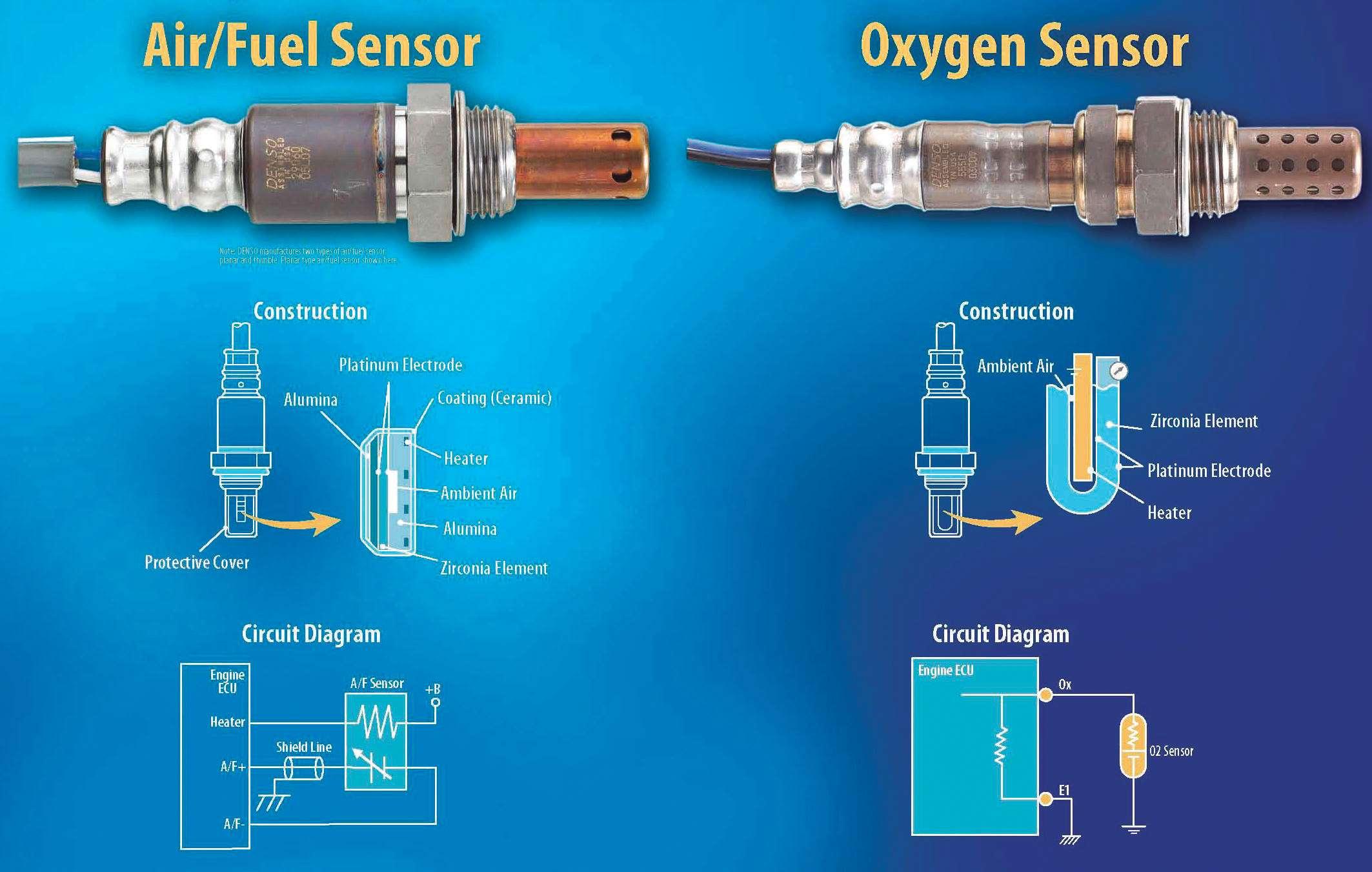
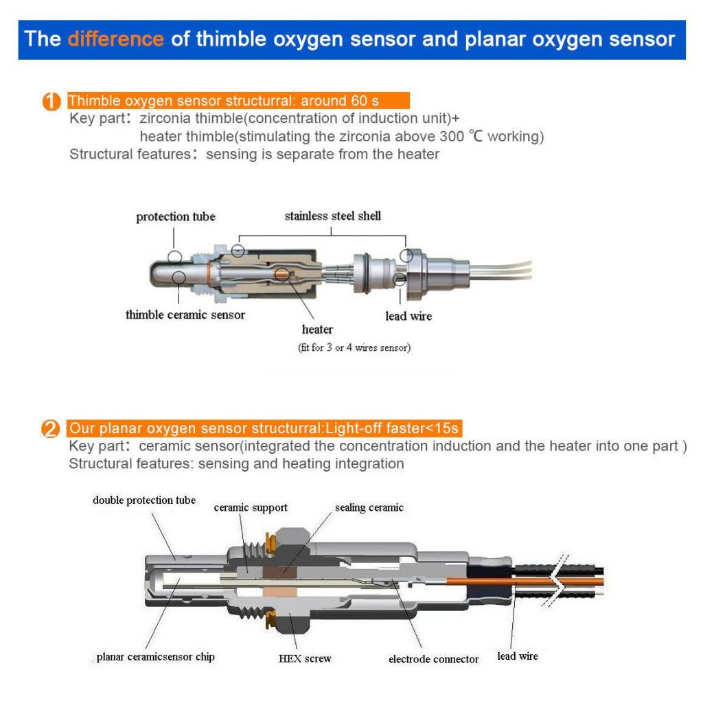
3.0 OXYGEN SENSOR TYPES & FUNCTION Unheated A one wire or two wire unheated oxygen sensor is the earliest and most basic type of sensor. One wire sensors employ only a signal wire, while two wire versions also have a wire going to ground. Unheated sensors require external heat and thus can only be located close to the

4 Wire Oxygen Sensor Wiring Diagram
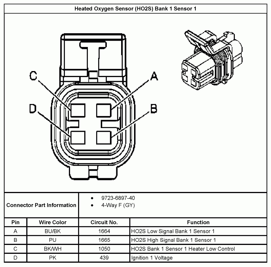
Step 3. Identify the different wires. One of the wires on the sensor is the ground wire, the other wire is the signal wire, and the remaining two wires are the heater circuit wires. All of these wires are coded with a color. Depending on the brand of the sensor the colors will vary. Identify your brand's color coding by referring to the chart.

42 4 wire o2 sensor wiring diagram
The wiring diagram for the Denso 4 wire o2 sensor typically includes the following colors for the sensor element wires: black, white, blue, and gray. The heater circuit wires are usually colored white and black. It is important to refer to the specific vehicle's wiring diagram or the sensor's documentation for accurate wire color coding.
4 Wire Oxygen Sensor Wiring Diagram Cadician's Blog
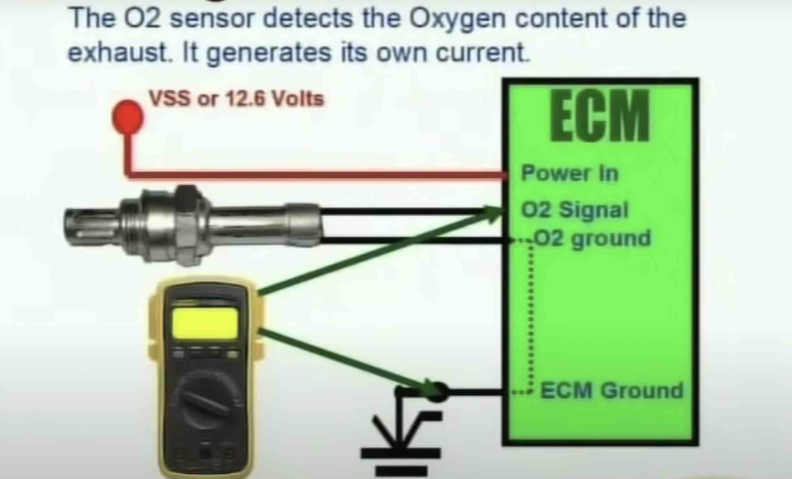
The O2 sensor wiring diagram is a crucial component in modern vehicles that helps monitor and regulate the air-fuel mixture for optimal engine performance. It provides valuable data to the engine control unit (ECU) by measuring the oxygen content in the exhaust gases. The diagram illustrates the electrical connections of the O2 sensor, which.

Corolla P0138 trouble code — Ricks Free Auto Repair Advice Ricks Free
Disconnect the oxygen sensor from the harness. Using a multimeter, measure the resistance across the heater circuit (typically the two white wires for Fords). Compare the reading to the manufacturer's specifications. If the resistance is out of spec, the sensor's heater circuit may be faulty and require replacement.
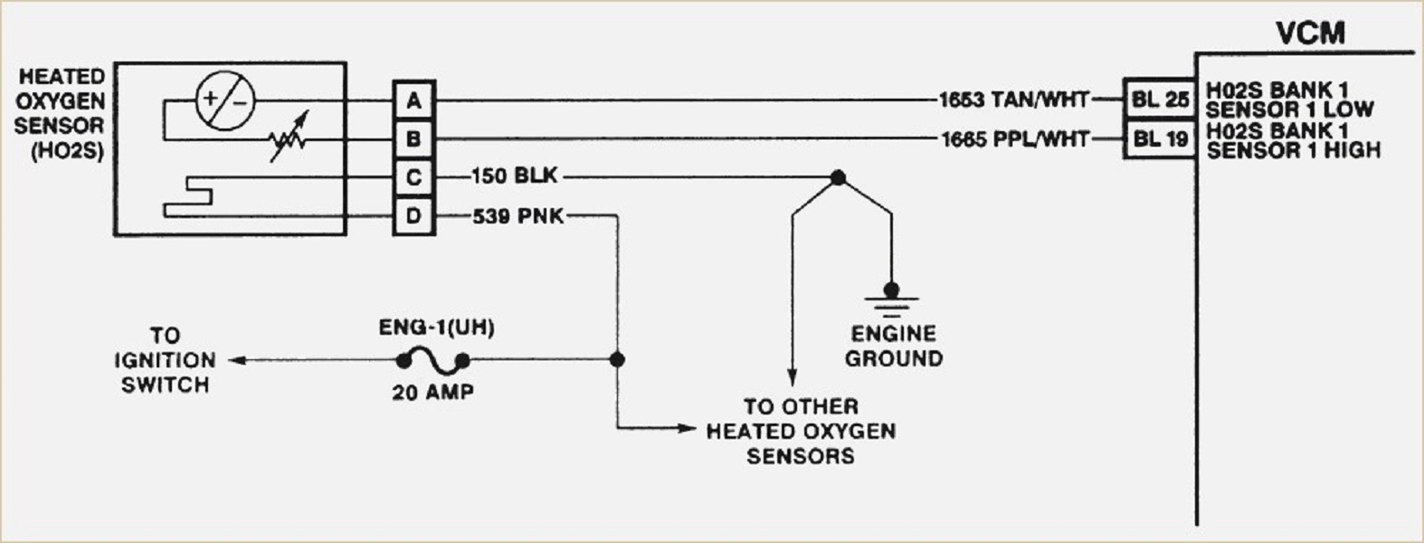
Jeep Oxygen Sensor Wiring Diagram
The 4-wire O2 sensor diagram also includes a connector, which serves as the interface between the sensor and the vehicle's wiring harness. The connector ensures a secure and reliable connection, preventing any signal loss or electrical interference. Understanding the wiring connection is crucial for proper installation and troubleshooting.
Bosch 4 Wire O2 Sensor Wiring Diagram Hastalavista 4 Wire O2 Sensor
The 4 Wire O2 Sensor Wiring Diagram for Honda vehicles is a crucial component that ensures optimal performance and fuel efficiency. This intricate diagram outlines the connections and circuitry required for accurate O2 sensor readings in Honda vehicles. With its four wire configuration, this O2 sensor plays a pivotal role in monitoring the air.
Toyota 4 Wire Oxygen Sensor Wiring Diagram Collection
Testing an O2 sensor with a multimeter is a simple process that can be done in a few steps. First, switch the multimeter to the ohmmeter mode and back pro be the heater wires. Then, connect the red lead of the multimeter to the heater hot wire and the black lead of the multimeter to the heater ground wire.
How To Test O2 Sensor With 4 Wires+ 4 Wire Oxygen Sensor Diagram
This video briefly explains how to install a universal 4 wire oxygen sensors. However, the concept is the same for 1, 2, and 3 wire universal sensors. If the.
bosch o2 sensor wiring diagram
Unleash the hidden potential of your vehicle's oxygen sensors as we embark on an electrifying journey through the intricate world of 4 wire oxygen sensor wiring diagrams. Beyond the realm of mundane automotive terminology lies a captivating universe of wires, connections, and the magnificent possibilities they hold.
bosch 4 wire o2 sensor wiring diagram RihaniNurlita
The diagram will show the location of the oxygen sensor, the type of sensor, and the color of the wires. The diagram may also show the location of other sensors and components that are related to the oxygen sensor. In this powerful guide, you will learn the wiring diagram of oxygen sensors such as 1, 2, 3, and four-wire o2 sensor wiring schematic.

[DIAGRAM] Gm Wiring Diagrams Oxygen Sensor Wiring For Dummiesputer Fron
The wiring diagram for a 4 wire oxygen sensor includes four wires: two for the oxygen sensor signal and two for the sensor's heater circuit. The oxygen sensor signal wires are responsible for transmitting the voltage signal produced by the sensor to the engine control module (ECM). The ECM uses this signal to adjust the air-fuel mixture.

O2 (Oxygen Sensors) Service
How to test Oxygen Sensor's Heater Wires. The first thing to do is to check the oxygen sensor's heater wires to know if the heating wires are broken. Just follow the method below: Start by switching the Digital Multimeter you have to the Ohmmeter mode. Then back probe the ground wire of the 02-sensor heater's hot.
Oxygen Sensor Wiring Harness Diagram Greenium
How to test 4 wire oxygen sensor . Testing a 4-wire oxygen (O2) sensor requires some basic tools and procedures. Here's a step-by-step guide on how to test a 4-wire O2 sensor: Tools and Materials: Multimeter. Safety goggles and gloves. Vehicle service manual (for reference) Steps: Safety Precautions: Ensure the vehicle is parked on a flat, safe.